Motor selection is a function of the well requirements. This article will introduce the drilling mud motor selection for its specification. At the same time, the drilling engineer cannot make a proper selection without a full understanding of the drilling mud motor specifications and limitations. And we, of course, shall cover them all.
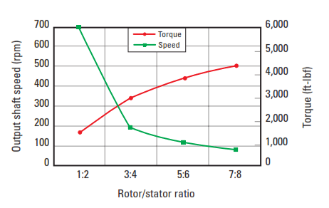
In brief, As the lobe number increases, the motor torque will increase, and the rpm will decrease. As in hard formation drilling with insert bits, the directional driller will choose a higher lobe configuration because insert bits do not tolerate high rpm, and more bit weight is required to drill in hard rock. The higher lobe configuration would be considered a slow-speed, high-torque motor.
If the well was to be drilled with a diamond or impregnated bit, the directional driller would choose the lower lobe configuration. These types of bits drill better with high rpm. The low lobe configuration would be considered high-speed, low-torque motors. PDC drill bits do better with higher rpm but also generate more torque. PDC bits may require a lobe configuration closer to the middle, such as a 3:4 or 4:5.
Drilling Mud Motor Specifications
There are 18 Drilling Mud Motor Specifications Items that can help in motor selection. These specs can be defined as follows:
- OD: Nominal outer diameter of the motor.
- Lobes: Rotor-stator lobe ratio for the power section.
- Stages: Power section stages within the stator.
- Flow: Normal operating flow range of the motor without a bypass nozzle. The overall flow through a mud motor can be increased by fitting a nozzle in the rotor and bypassing some flow through the center of the motor.
- Max flow with bypass: Maximum flow allowed with bypass nozzle; the limit is dictated by the flow through the driveshaft.
- Rev/unit volume: Number of revolutions per unit of fluid pumped through the motor.
- Speed: Revolutions per minute for an unloaded motor operating within the normal flow rate range.
- Operating torque: Torque output at recommended differential pressure levels for extended motor life.
- Differential operating pressure: The recommended maximum differential pressure for extended motor life is 80% of the differential pressure at maximum motor horsepower. If drilling conditions are favorable, the pressure differential may reach the maximum. Good drilling practices should prevail.
- Max power: Maximum power that the motor is capable of delivering.
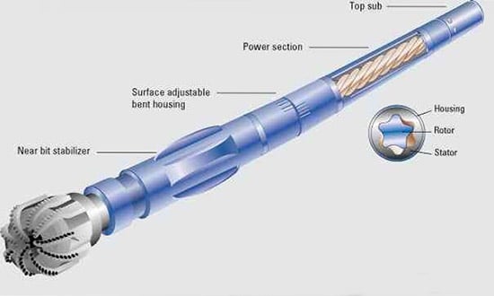
- Length: Nominal length of the motor, including the top sub/dump valve.
- Bend to bit box: Length from the shoulder of the bit box to the bend of the motor.
- Stabilizer to bit box: Length from the shoulder of the bit box to the center of the bearing housing stabilizer.
- RNBS bit to bend: Length from the shoulder of the bit box of the rotating near-bit stabilizer drive shaft to the bend of the motor.
- RNBS bit to stabilizer: Length from the shoulder of the bit box of the rotating near-bit stabilizer drive shaft to the stabilizer on the RNBS drive shaft.
- Weight: Nominal weight of the motor.
- Working overpull: The maximum load that can be applied to the motor, based on the strength of the bearing assembly, if the bit is stuck. Operations can continue if the bit comes free without exceeding the working overpull.
- Absolute overpull: The maximum load that can be applied to the motor, based on the strength of the bearing assembly, if the bit is stuck. Exceeding the absolute overpull may cause the motor to part.
Drilling Mud Motor Selection
Previously, in the Drilling Mud Motor Components article, we discussed each component in detail. Now, we must understand that the Selection of a drilling mud motor depends mainly on your knowledge of its specifications and components.
Selection Of Drilling Mud Motor Power Section
Rotor/stator lobe ratio
The lobes on a rotor and stator act like a gearbox. It affects the drilling mud motor specification as their numbers increase for a given motor size, the motor’s torque output generally increases and its output shaft speed generally decreases. Figure 1 shows an example of the general relationship between power section speed and torque and the power section lobe configuration. Because power is defined as speed times torque, a greater number of lobes in a motor does not necessarily produce more horsepower. Motors with more lobes are actually less efficient because the seal area between the rotor and stator increases with the number of lobes.
Motor mechanical power is calculated as follows:
HPmechanical = T x SR / 5252
Where:
- HPmechanical = motor mechanical power, hp
- T = output torque, ft-lbs
- SR = drive shaft rotary speed, rpm
Rotor/stator interference fit
The difference between the size of the rotor mean diameter (valley to lobe peak measurement) and the stator minor diameter (lobe peak to lobe peak) is defined as the rotor/stator interference fit (Fig. 2).
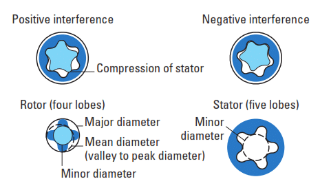
Motors are usually assembled with the rotor sized larger than the stator internal bore under planned downhole conditions. This produces a strong positive interference seal called a positive fit.
Motors run with a rotor mean diameter greater than 0.022 in., greater than the stator minor diameter at downhole conditions, and very strong (capable of producing large pressure drops). This produces a strong positive seal called a positive interference fit.
When higher downhole temperatures are anticipated, the selection of mud motor specification shall be targeted, reducing the positive fit during motor assembly to allow for the swelling of the elastomer. The mud weight and vertical depth must also be considered because they influence the hydrostatic pressure applied to the elastomer.
The interference fit is predetermined using software such as PowerFit. Considering mud motor specifications (type and size, elastomer type, and mud type), the program will calculate the “recommended interference” for the expected differential pressure, drilling fluid density, and expected bottom hole circulating temperature.
The common material for stator elastomers is nitrile rubber (good for most applications to about 280°F). An elastomer made of highly saturated nitrile can be used for more challenging applications. It is resistant to chemical attack and can be used at temperatures up to 350°F.
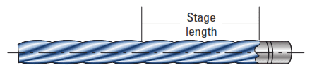
Spiral stage length
The stator stage length is defined as the axial length required for one lobe in the stator to rotate 360° along its helical path around the body of the stator. However, the stage length of a rotor is not equivalent to the stage length of its corresponding stator. A rotor has a shorter stage length than its corresponding stator. The equation that describes the general relation of the rotor stages to the stator stages is
Rotor stages = (n+1) / n x Stator stages
where
n = number of rotor lobes.
Stage length is dependent on the lobe pitch angle of the spiral. As the pitch angle increases, resulting in a tighter spiral and shorter stage length, the force vector perpendicular to the longitudinal axis of the rotor (torque) and the volume of the cavity within the stage decrease. This results in a reduction of torque output and an increase in the motor’s speed. Conversely, a decrease in pitch angle produces a longer stage length, resulting in an increase in torque and a decrease in speed. This is how stage length affects the selection of mud motor specifications.
Long-stage motors usually produce higher torque and fewer revolutions per minute than short-stage motors. As previously mentioned, the drawback for long-stage motors is that as the seal length along with the rotor/stator increases with stage length, the seal’s and speed’s efficiency decrease. The primary application for long-stage designs is air drilling.
Number of stages
For a power section with a set lobe ratio, more stages increase the number of fluid cavities in the power section. Each cavity can hold pressure, so as the number of cavities increases, the total pressure drop over the power section increases. Therefore, the mud motor specification for total pressure drop and stall torque capability theoretically increases linearly with the number of stages.
In the same differential pressure conditions, the power section with more stages will maintain speed better. Since there will be less pressure drop per stage, there will be less leakage.
Pressure drop per stage
The maximum designed pressure drop per stage is a function of the lobe profile and the hardness of the elastomer lining. Changes in the hardness of the elastomer affect not only the pressure drop but also the resiliency and life of the elastomer.
Near Bit Stabilizer (RNBS)
In the mud motor specification section, we defined the term Rotating near-bit stabilizers (RNBS) to bend & stabilizer. RNBS are available as a replaceable sleeve on the drive shaft bit box or as a short sub run below the motor. The subs can be used with both mud-lubricated and oil-seal-bearing motors.
All RNBS have spiral blades to reduce drag while rotating. RNBS helps to eliminate hole spiraling and reduce drag while sliding. This increases overall ROP.
Bearing section
In the drilling mud motor bearing section, motor manufacturers offer several designs. We here will consider the common design of oil-sealed bearings and their application to help you better selection of the proper drilling mud motor specification.
Oil-sealed bearings
Oil-sealed bearing assemblies are provided in several motor sizes, commonly 6 3⁄4 in. and smaller. They should be considered for the following conditions:
- Underbalanced drilling, especially with dry air, provides poor lubrication for mud-lubed bearings
- Run times less than 100 hr
- Multiple short runs before returning to the base for maintenance
- Very low bit pressure drop can cause mud-lubricated bearings to be under-lubricated.
Conditions that are not favorable for oil-sealed bearings are the following:
- Low-gravity solids above 8%
- Mud weights 14 ppg or greater
- Aggressive drilling fluids attack elastomers and seals.
Mud-lubricated bearings
The axial bearings consist of multiple mud-lubricated ball races that support the WOB load when drilling and the hydraulic down thrust when circulating off-bottom, drilling with less than the balanced WOB or back reaming.
Other Factors Affecting Selection Of Drilling Mud Motors Specification:
Range of flow rates allowable:
Each size and type of PDM is designed to take a certain range of fluid volumes. The proper selection of drilling mud motor specification for hole cleaning issues will be the multilobe motors, as they have a broader flow rate range and a much higher maximum allowable flow rate than 1:2 lobe PDMs of the same O.D. This gives better hole-cleaning capability, which is useful when the rate of penetration ROP is high.
No-load Pressure Loss:
This term is a certain pressure loss needed to overcome the rotor/stator friction forces and cause the drilling mud motor to turn off BTM. This pressure loss and motor RPM are proportional to the flow rate. Their values are known for each size and type of PDM. The no-load Pressure Loss is usually no greater than 100 psi.
Drilling Mud Motor Differential Pressure (Pmotor):
Drilling Mud Motor Differential Pressure can be defined as the increase in pressure as the bit touches the bottom and effective WOB is applied,
Pmotor = P on bottom – P off bottom
Motor torque increases in direct proportion to the increase in drilling mud motor differential pressure. For a multilobe motor, it can be 500 psi or even more.
There is a maximum recommended value of drilling mud motor differential pressure, which is an important element of the mud motor specification. At this point, the optimum torque is produced by the motor. If the effective WOB is increased beyond this point, pump pressure increases further. Pmotor increases to a point where the lining of the stator is deformed. The rotor/stator seal is broken, and the mud flows straight through without turning the bit. The pump pressure reading jumps sharply and does not vary as additional WOB is applied. This is known as stall out condition.
Recent studies have shown If the PDM is operated at 50%-60% of the maximum allowable motor differential pressure, the same performance should be achieved as when operating at 90% of Drilling Mud Motor Differential Pressure.
Pressure Drop Across The Drilling Bit (Pbit):
For a given mud weight and flow rate, the TFA of the bit nozzles determines the pressure drop across the bit. The smaller the TFA, the greater the bit pressure drop. This affects the volume of mud diverted to cool the bearings.
The greater the percentage of mud diverted, the greater the wear on the bearings. For every make and type of Drilling Mud Motors, there is a certain recommended value of Pbit. This should not be exceeded. For example, In ANADRILL multilobe motors, Pbit must be in the range of 500-1500 psi.
Rotor Nozzle
Most multilobe motors have a hollow rotor. This can be blanked off or fitted with a jet nozzle. When the standard performance range for the motor matches the drilling requirements, a blanking plug is normally fitted. The rotor nozzle can be easily replaced on the rig. (It normally entails removing the dump valve first). Use of this rotor nozzle can:
- Increase the total mud flow through the motor (e.g., in performance drilling for better hole cleaning).
- Reduce the Drilling Bit RPM at high flow rates. This is a useful option when using a conventional tri-cone bit. It helps to prolong the bit life by reducing wear on the bit bearings, etc.
Mud temperature
The system circulating temperature is a key factor in selecting mud motor specification as it dictates the amount of interference in assembling the rotor/stator. The higher the anticipated downhole temperature, the less compression is required between a rotor and stator.
The reduction in interference during motor assembly compensates for the swell downhole of the elastomer because of temperature and mud properties. If there is too much interference between the rotor and the stator at operating conditions, the stator will experience high shearing stresses, resulting in fatigue damage. This fatigue leads to premature chunking failure. Failure to compensate for stator swell resulting from the anticipated downhole temperature is a leading cause of motor failure.
Drilling Fluids
Mud motors are designed to operate effectively with all oil-based mud and water-base drilling fluids and oil-emulsion, high-viscosity, and high-density drilling fluid types, air, mist, and foam.
Drilling fluids can have many different additives, some of which harm the stator elastomer and stainless-steel/chrome-plated rotor.
Chlorides in mud can severely corrode the chrome plating on standard rotors. In addition to the damage caused to the rotors by corrosion, the rough edges left on the rotor lobes damage the stator by cutting the top off the elastomer in the stator lobe profile. These cuts reduce the effectiveness of the rotor/stator seal and cause the motor to stall (chunking the stator) at low differential pressure.
For oil-based mud (OBM) with supersaturated water phases and salt muds, tungsten carbide–coated rotors are recommended. Nonmagnenonmagneticnts, for instance, non-magnotators, can improve the motor’s life while drilling in H2S environments. Although nonmagnetic snonmagneticder (more robust) than regular steel and thus helps to reduce sulfide stress cracking, focusing on the drilling fluid system is the best preventative measure.
Lost Circulation Material
Lost circulation material (LCM) can cause two problems when pumped through a motor as follows:
- The material can plug off inside the motor, usually at the dump valve if one is used or at the top of the output shaft or the radial bearing.
- It can cause stator wear.
However, LCM can be used with some mud motors if certain precautions are followed:
- Add the LCM evenly—avoid pumping a large slug of material
- Minimize the use of hard, sharp-edged materials such as nut plugs, coarse mica, and calcium carbonate chips because these can cause stator wear by abrasion
- if possible, do not pump concentrations greater than 50 ppg medium nut plug or equivalent.
Although these guidelines help minimize the plugging problems associated with LCM, they cannot eliminate the possibility of plugging the motor or bearing section.
Dogleg
Rotating a motor in a high-dogleg interval in a well can damage the stator. The geometry of the wellbore causes the motor to bend and flex, especially if the motor has a bent housing. Because the stator is the most flexible part of the motor, it bends the most. As the stator housing bends, the elastomer pushes on the rotor and bends it, which causes excessive compression on the stator lobes and can lead to chunking.