Drill string design Calculations are made to help you select items from a list of ready-made Drill string components, not deciding what an individual component will look like. The objectives of our design efforts should be to:
- Keep the maximum stress at any point in the drill string less than yield strength derated by a design factor.
- Select components and configure assemblies to retard fatigue as much as economically practical.
- Provide equipment that is resistant to hydrogen sulfide if H2S is expected.
This Article covers simple drill string design steps for vertical and directional wells. Loads applied by tension, torsion, combined tension and torsion, burst pressure, collapse pressure, slip crushing, and stability forces are considered. Design steps to reduce fatigue damage are also covered.
Many factors must be considered in the drill string design, such as:
- Total depth.
- Hole size.
- Mud weight.
- Overpull.
- Bottom Hole Assembly Components.
- Hole angle.
- Pipe weights and grades.
- Corrosive environment.
- Ability to fish tools out of the hole. (Fishing In Drilling)
Drill String Design Calculations Steps
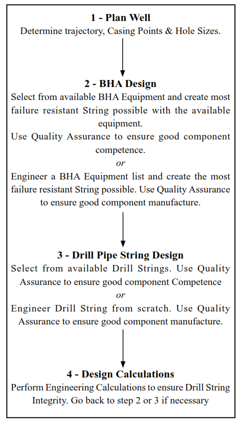
Design is a multi-step process, which usually begins at the bottom of the string and works upward. The steps and considerations in the Figure below will be helpful in most design situations.
Plan Well
Basic Well Planning knowledge is essential to understanding the Drill String design process. Information from the Planned Well is also essential to carrying out the Drill String Design process and selecting the required Drill String equipment. This will include the well bore & Casing sizes, CSG setting depths, well trajectory, and possible problems that may be incurred.
BHA Design In Drill String
As well as Drill Collars the BHA may comprise many types of specialist equipment. The BHA, by the loose definition used for this design manual, encompasses equipment that is run with a compressive force acting upon it (when calculated using the pressure area method), which may include the following:
| Item | Common Abbreviation |
|---|---|
| Drill Collars | DC |
| Mud Motors, Turbines PDM | PDM |
| Measurement Whilst Drilling | MWD |
| Heavy Weight Drill Pipe | HWDP |
| Specialised Drill Pipe | – |
| Jars | – |
| Stabilizers | Specialized Drill Pipe |
| Drilling Subs | – |
In Bottom Hole Assembly Components, Types, Behavior article, we shall cover the following subjects:
- Main Categories Of Bottom Hole Assembly BHA Used In Oilfield
- Bottom Hole Assembly BHA Drilling Components:
- How Drilling BHA Act / BHA Behaviour
- Rotary BHA Types
Furthermore, we recommend reading the BHA Design article. This article goes in-depth with selection tips and calculations for each of the BHA components.
Drill Pipe String Design
The first thing to consider while running the drill string design calculation is to check if the drill pipes you will use will sustain the drill collars and BHA loads in the worst case, which is stuck.
Tension Design Nomenclature
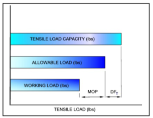
The basis for selecting various pipe grades to make up a drill string is always maintaining at least the desired Margin of Overpull (MOP) at all points in the string. This is accomplished by adding the lowest pipe grade, a joint at a time, starting from the top of the BHA and working upward. Each joint must support the BHA weight plus the drill pipe below that joint. When the working load (Pw) is reached for that drill pipe grade, the drill pipe is switched to a higher grade. This process continues until the string is complete. Tensile design nomenclature is reviewed below and illustrated in Figure 1.8.
Definitions
- Tensile Load Capacity (P): This is the calculated tensile pull to yield the pipe body. The tensile capacities of the Drill Pipe are given in Section 3, Table 3.1
- Design Factor in Tension (DFT ): The factor used to derate the tensile load capacity to obtain allowable load (PA)
- Allowable Load (PA): This is the maximum load we are comfortable placing on the pipe including an allowance for possible trouble. It is the tensile capacity derated by a design factor.
- Margin Of Overpull (MOP): The design has excess pull capacity above the working load (P ) to compensate for expected drag, possible sticking, slip crushing, and the effect W of the circulating pressure on tension.
- Working Load (PW): Working Load is the expected maximum tension that will occur during normal operations.
Note: Like the “Nominal Size” of Drill Pipe, the “Nominal Weight” of Drill Pipe is what we call it, not what it actually is. For example, 19.50 lb/ft Drill Pipe doesn’t actually weigh 19.50 lb/ft. Its approximate real weight in air is called the “adjusted weight” or “air weight” and will be something between 20.89 lb/ft and 22.60 lb/ft depending on the Grade of Pipe, the Tool Joint, and whether or not the contractor bought standard Tool Joint diameters. This adjusted weight is the one to use for design and displacement calculations. Nominal weights should be used only to communicate the type of pipe we are dealing with.
Calculate Allowable Load
The allowable Drill Pipe Load is calculated using the following:
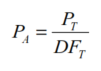
Where:
- PA= Maximum allowable Tensile Load
- PT= Pipe Tensile Capacity
- DFT= Design Factor for Tension
Set Maximum Over Pull
MOP is the desired amount of excess tension above the working load (P ) to account for hole drag, provide excess pull capacity if the pipe becomes stuck, and compensate for the “piston” effect of circulating pressure on tension. The first two elements are determined by local conditions or company policy. The effect of circulating pressure can be estimated by the following:
- ΔP = The estimated increase in Drill Pipe Tension due to circulating pressure (lbf)
- ΔPBit= Pressure Drop Across Bit (psi)
- Ai= Drill Pipe Internal Area (in2)
Learn more about the Margin Of Overpull & Drill Pipe Failure
Calculate Working Load
Maximum Working Load (P ) is the allowable load minus the Margin of Overpull:
PW= PA-MOP
- Pw= Working Load (lbf)
- PA= Pipe Tensile Capacity (lbf)
- MOP = Margin of Overpull (lbf)
Calculate Maximum Length Of The Drill Pipe Sections
The Drill Pipe string may consist of different grades. Therefore, the next step is to determine the lengths of each drill pipe section.
Slip Crushing In Drill String Design
Drilling slips exert hoop compression on the drill pipe, which can deform the pipe if conditions are unfavorable. It will be important in drill string design to check whether slip crushing may happen to your drill pipes.
Read More about Slip Crushing Formulas.
Drill Pipes Collapse Pressure
If the drill pipe is subjected to an axial tensile load, the collapse pressure ratings from the tables, which will be used in the drill string design, must be derated. So, you will have to calculate the adequate drill pipe collapse pressure.
Drill Pipes Burst Pressure.
The differential pressure acting across the drill pipe wall due to an internal pressure more significant than the external pressure is known as the burst load.
Learn more about Drill Pipe Burst Pressure Calculations & Rating.
Tool joint Torsional Strength
What will happen if the torque produced while drilling equals the M/U torque of drill pipes’ tool joints or the torsional strength of drill pipes? So, understanding drill pipe tool joints is essential during the drill string design calculations.
Stability Forces and Drill Pipe Buckling In String Design
Given that full circulation is established with the drilling bit off the bottom, the tendency of stability forces to buckle drill pipe can safely be ignored in drill string design, which greatly simplifies design calculations. However, if the bit pressure drop is increased while the bit is on the bottom, the drill pipe can buckle above the BHA (with resulting fatigue damage) even though the point of zero tension is still below the top of the BHA. This occurs because the pipe cannot stretch to accommodate the increase in internal pressure. If buckling happens, however, it will be temporary. Once enough holes have been made to accommodate the stretch that would have occurred had the pipe been hanging freely, pressure-induced buckling will disappear.
Whether or not the drill pipe will temporarily buckle depends on operating conditions at the time. Shallow drilling, thin-wall drill pipe, large changes in bit pressure drop while drilling, and high bit weight for available BHA weight all favor temporary pressure-induced drill pipe buckling. The following rule will eliminate pressure-induced buckling:
Any time a pump rate increases while the bit is on the bottom, pick up the drill string until a gain in weight is first noticeable. This allows the string to stretch and relieves the tendency to buckle.
Read More About: Buckling in Drill String
Heavy Weight Drill pipes
The field tests showed that the higher the stiffness ratio at the transition zone, the greater the fatigue build-up. In Heavy Weight Drill Pipe Specs & Selection, we shall cover the following subjects:
- Definition
- Function
- Specs
- Specs Sheets from Work Strings International
- Specs Selection And Design
- The use of HWDP offers the following advantages.
Directional Drilling String Design for Deviated wells
In drilling inclined and horizontal wells, there are two additional factors, which are not present in vertical wells, that must be considered: (1) The frictional forces between the drill string and the hole, (2) The ability to use the drill pipe or HWDP to provide weight on the bit without buckling.
The following Subjects Shall Be Covered In Directional Drilling String Design for Deviated wells Article:
- Drill String Torque & Drag Calculations
- Critical Hole Angle Calculations
- Determination of Friction Coefficient
- Factors that Affect Torque and Drag
Drill String Design for High Angle and Horizontal Wellbores
The objectives of drill string design in horizontal wells are:
- Provide adequate weight on a bit without buckling the drill pipe or heavy-weight drill pipe.
- Ensure that the components in the drilling assembly are not subjected to mechanical loads that exceed their design limitation.
In the Drill String Design Of Horizontal Wells Article, We shall cover the following:
- How Drill String Design In Horizontal Wells Differs From In Vertical Wells
- The objectives of drill string design in horizontal wells are:
- The maximum weight on bit without buckling the drill pipe can be calculated in two steps: Calculate the maximum weight that can be applied on the bit without buckling the drill pipe below the tangent point.
- Calculate the maximum weight that can be applied on the bit without buckling the drill pipe above the kickoff point.
- Calculation of Axial Mechanical Forces In High Inclination / Horizontal Wells
- Summary for high angle wells Drill String Design
Information is rich. But I need Index calculation format and procedure when the running tool and landing string lands in the wellhead with high and low tide.