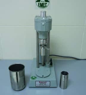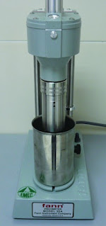
A drilling fluid viscometer or rheometer is used for obtaining fluid rheology (apparent viscosity, plastic viscosity, yield point, and gel strengths) (check also Yield Point In Drilling Mud Formula), which is a measure of the resistance of a fluid to flow. Several models are available, powered by a hand-crank or electric motor. The instrument comprises a solid pivoted cylindrical bob that is restrained by a torsion spring and connected to a torsion dial. The cylindrical bob sits inside a cylindrical outer sleeve that can be rotated at selected speeds, with a narrow annular clearance between the bob and the sleeve. Six-Speed Viscometer before and after assembly. In this article, we will handle the rheometer test method.
General Idea For Rheometer Test Method
In the rheometer test method, the mud sample is placed in a heating cup to bring it to a designated temperature for measuring the rheology (usually 50°C or 120°F, but higher temperatures may be specified for high-temperature wells). The heating cup sits on the adjustable viscometer platform, which is raised until the cylindrical bob and rotating outer sleeve are immersed in the mud sample. Once the mud sample reaches the required temperature, the outer sleeve is rotated at selected speeds, and the resultant deflection of the cylindrical bob can be read off the torsion dial, high viscosity fluids producing larger deflections.
Basic viscometers only give 600, 300, and 3 rpm readings. Most drilling fluid viscometers give 600, 300, 200, 100, 6, and 3 rpm readings, while some also give 60 and 30 rpm readings. The apparent viscosity, plastic viscosity, and yield point can all be calculated from the 600 and 300 rpm readings, while the gel strength is given by the 3 rpm reading. Gel strengths are usually recorded after 10 seconds, 10 minutes, and occasionally 30 minutes. The correct procedure for the rheometer test method is as follows:

- Fill the heating cup with the fluid sample and place on viscometer platform.
- Adjust the viscometer platform until the fluid sample level reaches the circumferential groove marked on the rotating outer sleeve.
- Rotate the outer sleeve to stir the fluid while the sample reaches the required temperature (usually 50°C or 120°F).
- Once at the required temperature, select the 600 rpm gear and wait for a steady deflection before recording the 600 rpm dial reading.
- With the motor still running, select the 300 rpm gear and wait for a steady deflection before recording the 300 rpm dial reading.
- Repeat the procedure for all the other dial readings.
- To measure the 10 second gel strength, stir the mud at 600 rpm for several seconds to breaks any gels, then select the low speed gear and switch off.
- After 10 seconds, switch the viscometer back on at 3 rpm and record the maximum dial deflection before the gel breaks, which is the 10 second gel strength.
- To measure the 10 minute gel strength, stir the mud at 600 rpm for several seconds to breaks any gels, then select the low speed gear and switch off.
- After 10 minutes, switch the viscometer back on at 3 rpm and record the maximum dial deflection before the gel breaks, which is the 10 minute gel strength.
- Repeat the procedure if the 30 minute gel strength is also required.
- The final step of rheometer test method is to wash the viscometer by carefully removing the rotating outer sleeve, which has a small slot that locks onto a pin. The cylindrical bob can then be wiped cleaned with a cloth or paper tissue, taking care not to bend the fragile assembly. The heating cup must be disconnected from the mains before cleaning.
The Equations Related To Drilling Fluid Viscometer Testing Procedures
The fluid rheology can be calculated using the following equations.
Apparent Viscosity = [600 rpm rheometer reading]/2, reported in cP (centipoise)
Plastic Viscosity = [600 rpm rheometer reading] – [300 rpm rheometer reading], reported in cP
Yield Point = (2 x [300 rpm reading]) – [600 rpm reading], reported as lb/100ft^2 Gel Strength readings are reported as lb/100ft^2
Viscometer calibration is a specialized procedure and faulty units should be returned for repair by trained technicians. Note that viscometers are available for 50 Hz and 60 Hz frequencies, so it is important to check that the frequency of the viscometer matches that of the power supply to ensure that the motor runs at the correct speed.
Plastic Viscosity tends to increase while drilling due to the build-up of ultra-fine solids in the drilling fluid. Some drilled solids are too small to be removed by the Solids Control Equipment, so they remain in the drilling fluid and are gradually eroded into ultrafine particles, along with other fine particles that are designed to pass through the shale shaker screens (check also shale shaker) (e.g. barite, calcium carbonate, etc.). The increase in solids results in an increase in friction between the solids, which increases the Plastic Viscosity of the drilling fluid.
In the Rheometer test method, yield Point helps to keep drilled solids and weighting materials (e.g. barite and calcium carbonate) in suspension. If the Yield Point is too low then solids will gradually settle out when circulation is halted during a connection or while tripping pipe out of the hole. Solids could then build up in a deviated part of the hole, or collect around the BHA, with the potential for getting mechanically stuck in the hole. Solids falling out of suspension will also reduce the mud density in highly deviated sections, resulting in a reduction in hydrostatic pressure when it reaches the vertical part of the hole when circulation resumes, with the potential for a well control incident.
If the Yield Point is too high then circulating pressures and ECD in Drilling will be high, with the potential for induced mud losses to the formation. Gel Strengths, which is a measure of the attractive forces between the particles when the drilling fluid is static, also need to be controlled. Progressive gels are another indication of high solids in the mud and will affect surge and swab pressures while tripping in or out of the hole. Higher gels will also require higher pump pressures to break circulation, which could increase the potential for induced mud losses to the formation