A definite time interval is always required for pumping the samples from a particular depth to the surface where they can be collected. When determined, This critical time interval is called “Drilling lag time” and can be measured in terms of pump strokes and time. This lag applies to all downhole information, including formation cuttings and the fluids (gas, oil, and water) that they contain.
Why it Should Be Accurate?
The lag always exists and changes continuously as the hole becomes deeper(as the annular capacity volume increases). As such, it is necessary to know the lag and apply it continuously to returning samples. Due to the factors which cause it to change, the lag must be frequently checked and corrected. With the above in mind, a lag determination is one of the most fundamental concepts that must be mastered by the logging geologist. This lag time will allow for correct correlation with real-time parameters such as depth and drill rate.
Factors Affecting Lag Time Calculations
Lag time is dependent on two factors;
- The volume of drilling fluid in the annulus, an increase in depth means an increase in annular volume, and hence an increase in lag time.
- The flow rate of the drilling fluid, the faster the drilling fluid is pumped into the borehole, the quicker it returns to the surface.
As the annular diameter gets larger (borehole washouts), the annular volume increases and so will lag time.
For a given annular volume, the lag time (in minutes) can be calculated by dividing the annular volume (bbls) by the flow rate (bbl/min). When using a time value, it should be remembered that if the flow rate changes, so will the lag. To compensate for such changes, lag time is also converted into pump strokes, so a change in pump speed (spm) will not affect drilling lag time.
How To Perform Lag Time Calculations
1) Calculation of Pump Output

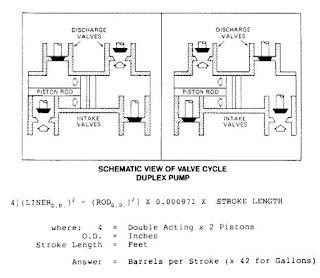
The first step in the calculation of lag time is the determination of pump output. There are several methods.
Once pump output has been determined, the output value should be placed in all forms necessary to perform future calculations. They are:
- Barrels per Minute bbl/min
- Gallons per Minute gal/min
- Barrels per Stroke bbl/stk
- Gallons per Stroke gal/stk
2) Annular Volume Calculations
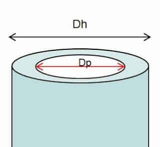
Annular Volume calculations, though a little longer, are more accurate. These calculations are based on the formula for determining the volume of a cylinder (πr2h).

Annular capacity in bbl/ft = (Dh^2 – Dp^2) ÷1029.4
Where:
Dh & Dp in inches
3) Drawing Well Model To Facilitate Lag Time Calculations
Once mud pump output has been determined, it will be necessary to draw a wellbore profile, illustrating and defining the various diameters and lengths. Included should be the inside diameters of the drilling riser, Casing, casing liner (One of Types Of Casing), and open hole, and the inside and outside diameters of the Drill Pipe, Heavy Weight Drill Pipe HWDP, and Drill Collar. Draw the well model using this information (Figure 3) and update it whenever necessary

Theoretical Calculations
These calculations assume that there are no washouts and no Under gauge Holes, and the open hole is the Drilling Bit diameter. Since most wellbores will suffer a certain amount of washout, (which increases the hole size) the theoretical lag is usually an underestimation.
This calculation is important when compared to tracer (actual) lag information. It can provide useful information concerning borehole conditions.
There are two methods used in calculating theoretical drilling lag time:
- Velocity Method – using annular velocities (ft/min)
- Volume Method – using annular volume (bbls)
Using the information from Figure 3, and a pump output of 425 gal/min (10.11 bbl/min) at 100 spm:
1 Velocity Method – using 24.51 x Q / (D^2 – d^2)
Where:
Q = flow rate (gpm)
D = borehole/casing inside diameter (inches)
d = drillpipe/drill collar outside diameter (inches)
Section 1:
Annular Velocity = 24.51 x 425 / (9^2 – 5^2)=186 ft/min
Annular Section = 6000 feet
Lag Time for Section = 32.26 minutes
Section 2:
Annular Velocity = 24.51 x 425 / (8.5^2 – 5^2)= 220.46 ft/min
Annular Section = 350 feet
Drilling Lag Time for Section = 1.59 minutes
Section 3:
Annular Velocity = 24.51 x 425 / (8.5^2 – 7^2) = 448 ft/min
Annular Section = 1400 feet
Lag Time for Section = 3.13 minutes
Total Lag Time = 32.26 + 1.59 + 3.13 = 36.98 minutes or 3698 strokes
These annular velocities will be useful when determining Equivalent Circulating Density (E.C.D.) and Pressure Losses within the circulating system.
2 Volume Method – using (D^2 – d^2) x 0.000971 x L
where: D = borehole/casing inside diameter (inches)
d = drill pipe/drill collar outside diameter (inches)
L = length of annular section (feet)
Section 1:
Annular volume = (92 – 52) x 0.000971 x 6000 = 326.25 bbls
Lag Time for Section = 32.27 minutes
Section 2:
Annular volume = (8.52 – 52) x 0.000971 x 350 = 16.05 bbls
Lag Time for section = 1.58 minutes
Section 3:
Annular volume = (8.52 – 72) x 0.000971 x 1400 = 31.60 bbls
Lag Time for Section = 3.12 minutes
Total Drilling Lag Time = 32.27 + 1.58 + 3.12 = 36.97 minutes or 3697 strokes
Actual Lag Time Calculations
The only way of obtaining an accurate lag is by measuring the time or strokes that some substance (a tracer) takes to return to the surface, after being introduced into the drill string.
Using Calcium Carbide To Calculate Actual Lag Time
The most commonly used tracer is calcium carbide, which, when it comes into contact with the water in the drilling fluid forms acetylene gas.
CaC2 + 2H2O ——> Ca(OH)2 + C2H2
This acetylene gas is detected by the gas detection equipment when it returns to the surface.
Using Solid Tracers To Calculate Actual Lag Time
If water is not present in the drilling fluid (an oil-based mud), then a solid tracer, such as rice, wheat, or cellophane can be used. Whenever a solid tracer is used, make sure that the material will pass through the bit jets.
Using Propane To Calculate Actual Lag Time
When air drilling, propane is injected into the system for actual lag time calculations.
Procedures Of Using Carbide To Calculate Actual Lag Time
Dropping a carbide serves two purposes.
- It allows for an accurate calculation of lag,
- Also, it serves as a check on the efficiency of the gas detection equipment. To compare carbides.
For efficiency purposes, carbides must be run consistently (i.e. using the same amount of carbide each time). There shall be a measuring cup in the mud logging unit for this purpose. Let’s assume the measured amount to be 100 ml.
- Carbides are normally wrapped in an “envelope” made of paper towels and scotch tape. The wrapping material must dissolve in the drilling fluid so it doesn’t block the jet nozzles.
- The safest place to insert this “carbide bomb” is in the pin of the next joint (or stand) of pipe going into the borehole. Ask the driller (Check also Driller Job Descriptions) to hold the next joint above the pipe in the slips, while you push the bomb inside the pin. Once in place, the number of strokes on the counters should be noted.
- The time or strokes it takes the tracer to travel to the bit must be taken into account. This “downtime” is easily measured (using Figure 3) by:
- Calculate volume in drill pipe = 4.276^2 x 0.000971 x 6350 = 112.73 bbls
- Calculate Volume in drill collars = 3.5^2 x 0.000971 x 1400 = 16.65 bbls
- Downtime = (112.73 + 16.65) / 10.11 bbl/min = 12.79 minutes or 1279 strokes
- This downtime must be subtracted from the total strokes when the tracer is detected.
The frequency of carbides is difficult to determine. Under normal circumstances, a carbide should be dropped at least once a day or every 300 feet, whichever is less. The best policy to follow, however, is to drop carbides as often as necessary.
Theoretical Lag Time Calculator
All you have to do is to enter the pump speed in gallons per minute, pump output in bbls/stroke & Annular volume in bbls.
