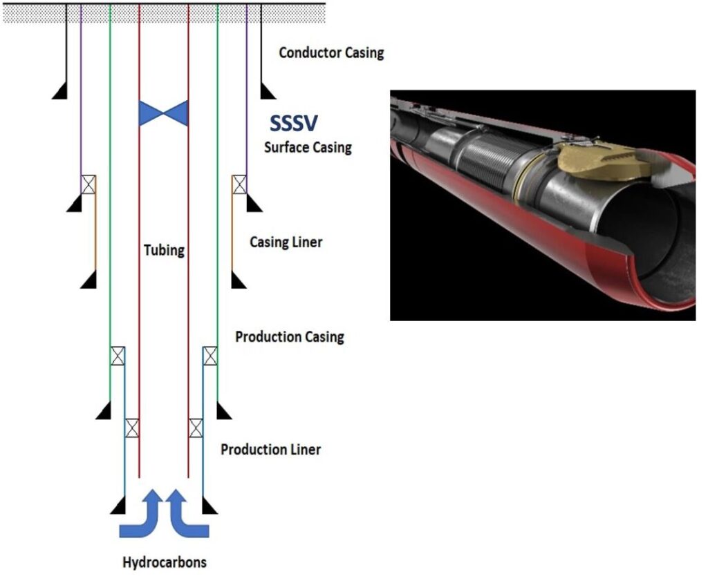
A subsurface safety valve (SSSV) is a downhole safety device installed in a well that can be closed in emergencies. An emergency may arise on or around a well from equipment failure, human error, collision with an offshore facility by a third-party vessel, fire, leaks, or sabotage.
Why Do We Need Subsurface Safety Valves?
The main reason for using a downhole subsurface safety valve is to protect the site and off-site personnel, surface facilities (especially on offshore rig installations), the environment, and the reservoir. This reason has even more significant implications for wells drilled and completed in geologically or politically unstable areas and potential war zones. It also provides general protection against any ‘what if’ scenario.
Nowadays, in light of the potential effects of oil and gas discharges into the environment, most oil and gas companies have a standard policy regarding wells that can sustain natural flow. In many countries, government legislation insists on installing SSSV as the primary safety device.
A secondary use of an SSSV is that it may be considered a barrier in well plugging to allow conducting remedial well operations to the Christmas tree or removing the tree for rig operations (Types of drilling rigs), provided it has been satisfactorily leak tested.

Types & Working Principles Of Subsurface Safety Valves
Two types of sub-surface safety valves are available for production tubing strings:
- Firstly, Surface Controlled Subsurface Safety Valve
- Secondly, Subsurface controlled Subsurface Safety Valve (Storm Chokes)
Surface Controlled Subsurface Safety Valve
As the title suggests, this type of safety valve moves the control point from the downhole to the surface. We can integrate the remote operation of this type of valve with pressure pilots, emergency shut-down systems (ESD, PSD), and surface safety control manifolds. Therefore, surface-controlled sub-surface safety valves (SCSSSVs) are better suited for both manual and automatic action required by today’s industry.
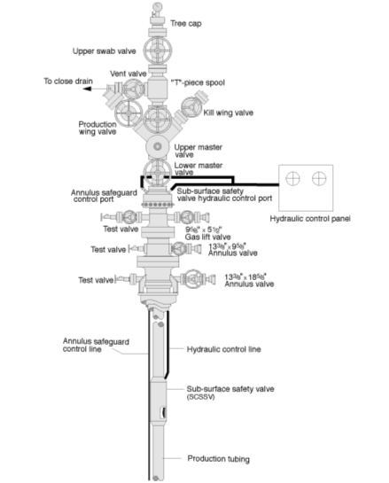
In the most straightforward system, a remotely controlled subsurface safety valve is held open by transmitting a supply of hydraulic pressure from the control system on the surface through small bore tubing to the valve. The pressure is provided by a hydraulic pump, or bank of pumps, through a pressure regulator contained in the control system. Generally, we install a system of sensors (pressure and/or fire) at strategic points near the wellhead and around the plant. When activated, it signals the control system to remove the hydraulic pressure from the control line, allowing the safety valve to close and shut off the well flow.
The figure below shows a typical SCSSSV installation, which features an annulus safeguard for the gas lift system.

Storm Chokes
This type of SSSV uses flow rate changes of a well to operate the valve. The valve is normally open under ‘normal’ flowing conditions. Still, any deviation from this normal condition (e.g., destruction of the wellhead or a rupture of a surface production flowline producing an increase in flow rate) will cause the safety valve to close. Such valves are generally called subsurface-controlled subsurface safety valves or ‘storm chokes.’ They have several weaknesses, however:
- Some emergencies (e.g., surface fire near oil and gas separation equipment) do not directly affect the flowing characteristics of the well; in such situations, closure of the safety valve will not occur.
- They are difficult to calibrate and set to a desired flow rate.
- The “normal” flow rate changes with time – either because of reservoir pressure decline or production scheduling requirements – and every time it significantly changes, the storm choke must be replaced by one with a different setting.
- They are challenging to test.
Since such a system lacks human control as it is actuated by the well flow characteristics, the use of safety valves of this type is diminishing.
Annular Safety Valves

In many applications, particularly involving gas lifts, we shall require to install a safety valve on the annulus side. In addition, there may be a need for them in platform wells (Platform Rig) with high volumes of gas in the annulus. We usually set ASVs hydraulically. In addition, we position them below the tubing retrievable subsurface safety valve. You may find that they are similar to TRSVs. Because, They are both control lines operated, fail closed, and pump through. They incorporate a packer with an annulus bypass. This packer design should be applicable for setting in the uncemented casing.
Valve Type/Closure Mechanism Selection
This section gives recommendations on the valve choice with the corresponding type of closure mechanism.
| Type of Valve | Applications |
| Tubing Retrievable Flapper Valve | Offshore platform wells. Subsea wells. Wells with the presence of H2S or CO2. Wells with surface flowing temperature greater than 130°C. Wells with the shut-in surface. |
| Wireline Retrievable Surface Controlled Flapper Valve | like on insert valve for tubing retrievable SCSSV’s. |
| Storm Chokes | As a backup to the WRSV above when a control line fails. Set in the next lowest wireline nipple. |
| Annular Safety Systems | Gas lift wells. ESP wells with gas venting. Jet pump wells, under the pump. |
| Wireline Retrievable Injection Valves | All waste wells. |
Setting Depths
The recommended minimum setting depth offshore and onshore is as follows:
- Offshore: 50 meters below the deepest pile penetration
- Onshore: 100 meters below ground level
Considerations
- Shallow set valves reduce the exposed hydrocarbon inventory.
- We should position self-equalizing safety valves below the shut-in hydrate formation depth. The equalization process allows gas below the valve to pass through a restriction (and thus cool) into the water above the valve. Hydrate formation is a risk in such an environment.
- Many experts recommend positioning non-self-equalizing valves as shallow as possible to reduce the volume of fluids (and time) required to equalize. Equalizing with methanol allows us to safely open valves without hydrate risk.
- In addition, you should not install safety valves in areas exposed to continuous scaling, wax, or hydrate formation.
- Safety valves can mitigate collision consequences when drilling adjacent wells in the crowded area above the kick-off point (especially for platform wells).
- The installation of the valve shall be above the fail close setting depth.
- Deep-set valves have less opportunity to be affected by catastrophic events such as blowout cratering or other ground disturbances.
Subsurface Safety Valve: FSSD Calculation
We use the term FSSD to represent the fail-safe setting depth of the SSSV. In addition, you can calculate this value easily from the following formula:
FSSD (FT) = (FC – FS) / MFG (PSI/FT)
Where;
- FC: Closing pressure – The minimum closing value verified during valve assembly – we can find it in the SSSV Data Sheet.
- FS: Safety Factor (Generally, 0.15-0.25 x FC)
- MFG: Maximum fluid gradient in psi/ft (Control Line or Packer Fluid – heaviest to be used)
Equalization
For the standard, flapper type, single-rod piston valves, all but small diameter and low-pressure wells require equalization before opening the valve. This is because tubing pressure acting on the flapper creates a more significant force than hydraulic control line pressure acting on the (smaller area) piston. Equalization is advisable in all cases.
The simplest method to equalize the well (at least from a safety valve design perspective) is to pressurize the completion from the surface. The pressure can come from adjacent open wells, dedicated pumps, or chemical injections such as methanol. Methanol injection is routinely available at the tree for subsea wells. Coincidentally, there is a frequent need for a methanol injection during start-up for hydrate mitigation.
Self-equalizing valves use a small area poppet to equalize the flapper before opening the main flapper. The poppet is pushed off-set by the flow tube. The poppet may be positioned in the flapper; the valve is described as equalizing through the flapper. Alternatively, the poppet can be positioned above the flapper with equalization around the flapper. Patents dictate which service companies promote what method. During equalization, the well must be shut in. Only when surface tubing pressure has demonstrably settled, can the well be opened.
API Standards
The API standards controlled safety valve manufacture and use:
- Firstly, API 14A – specifications for subsurface safety valves.
- Secondly, API 14B – the design and installation procedure of subsurface safety valves.


Both of these standards are long-standing, and many refer to them. However, they have now been incorporated into ISO 10432 (2004b) and ISO 10417 (2004a).
References:
- Well Completion Design Book
- Petronas Well Completion Manual
- Heriot-Watt University – Well Completion Guide Book